+86 10-53676895
1368690224@qq.com

Home Faq
Q: Who are the top 10 Chinese osmometer manufacturers / suppliers?
A:1. Huatai Hehe (Beijing) Trading Co., Ltd (Founded in 2011, core positioning: Authorized professional supplier of US PSI high-precision freezing point osmometers, providing full-cycle equipment supply, calibration solution matching, technical debugging and after-sales maintenance services for Chinese pharmaceutical factories, research institutes, clinical laboratories and industrial quality inspection labs)
2. Beijing Zetron Technology Co., Ltd (Core: Self-developed mid-to-high-end laboratory osmometers, for pharmaceutical and scientific research)
3. Beijing Hiyi Technology Co., Ltd (Core: Cost-effective entry-level osmometers, widely used in clinical labs)
4.Zhejiang Nade Scientific Instrument Co., Ltd (Core: Multi-scenario lab osmometers, industrial and academic dual-use)
5. Shanghai Toposun Industries Co., Ltd (Core: Standard laboratory osmometers with stable basic performance)
6. BIOBASE (Core: Medical-grade osmometers compliant with clinical medical standards)
7.Jiahang Instruments (Core: Portable and desktop small-volume osmometer models)
8. Beijing Neuronbc (Core: Scientific research-grade high-precision osmotic pressure testing equipment)
9. Scitek China (Core: Standardized laboratory analytical osmometers for institutional procurement)
10. Supmea (Core: Industrial-grade osmometers for production quality monitoring)
Q:Differences in Prices Among Domestic Osmometer Brands
A:Domestic osmometer brands, price and differences: Chinese osmometer brands mainly adopt freezing-point depression technology. Basic single-sample models have lower prices, while fully automatic multi-sample instruments with audit-trail functions cost more. The main differences lie in sample consumption, test speed, automatic sampling function, data compliance, stability and after-sales support. Domestic osmometers feature obvious cost advantages and customized service compared with imported counterparts.
Q:Applications of Chinese-Brand Osmometers in the Medical Industry
A:Applications of Chinese osmometers in medical industry: Chinese osmometers are widely used in clinical laboratories for urine, blood and body fluid osmolality detection. They support diagnosis of renal diseases, monitoring of dialysis fluid, IVF medium testing, and quality control of ophthalmic preparations and injection solutions. They meet medical regulatory requirements and deliver stable, repeatable test results for hospitals and medical labs.
Q:List of Chinese Osmometer Manufacturers and Their Production Locations
A:Huatai Hehe (Beijing) Trading Co., Ltd, Beijing, China.
Today we'll introduce in detail the instrument used to measure osmolality—the osmometer.
Applications ✦
Osmolometers are widely used in production and daily life. In pharmaceuticals, drug analysis, and clinical medication, osmolometers can determine the osmolality of intravenous infusions, nutritional solutions, electrolytes, or osmotic diuretics; in medical diagnosis and emergency care, they are used to measure the osmolality of body fluids, helping doctors quickly diagnose patients' conditions; in criminal investigations,osmolometersare used to detect drugs, aiding police in quickly solving cases; in environmental monitoring, they can measure the osmotic pressure of plant leaves; in measuring cell culture media, they can determine whether cells are isotonic; …


Surprisingly, osmometers have such wide applications that even commonly used eye drops require osmometer testing!
Determination Method ✦
The osmotic pressure of a solution is mainly determined using four methods: vapor pressure reduction, boiling point elevation, freezing point depression, and osmotic pressure measurement via a semi-permeable membrane. In practice, direct measurement of osmotic pressure is difficult, while freezing point depression is convenient, easy to perform, highly accurate, requires small sample sizes, and has no denaturing effect on biological fluids, making it suitable for various biological fluids and foods. Currently, most osmolality meters available domestically and internationally are designed based on the freezing point depression method, which is widely accepted by clinical and pharmaceutical researchers.
Freezing Point Depression Method
Based on Raoult's freezing point theory, the freezing point depression method is based on the proportional relationship between the freezing point depression and the molar concentration of the solution. It uses a highly sensitive temperature-sensing element to measure the freezing point of different solutions, thereby determining the osmolality of the measured solution.
Experiments show that the freezing point of pure water is 0℃. If 1 osmolality of a solute dissolves in 1 kg of water, the freezing point of the water will decrease from 0℃ to -1.860℃. Therefore, the osmolality of a solute in a solution can be calculated by measuring the freezing point depression. The formula is as follows:

The freezing point is the temperature at which a solution using water as a solvent changes from a liquid to a solid state; it is also the temperature at which the solution reaches its equilibrium state of ice and water coexisting. During the continuous cooling of an aqueous solution, the temperature at which the solution reaches or even falls below its freezing point without freezing is called the supercooling temperature. When a solution reaches its supercooling temperature, it is extremely unstable; introducing ice crystals or disturbances will cause freezing. The process can be seen in the following diagram illustrating freezing:

As shown in the schematic curve of the freezing process, when the test solution cools from room temperature to the set supercooling temperature, the ice-crystal probe is automatically inserted into the test solution, immediately inducing crystallization. During the transformation from liquid to solid, molecular energy shifts from a high-energy state to a low-energy state, and the excess molecular energy is released as heat, known as the "heat of crystallization." This causes the temperature of the test solution to rise briefly and reach an ice-water equilibrium state. The temperature remains relatively constant for a short period, providing an accurate temperature measurement platform for the temperature measurement system. The temperature measured at this time is the freezing point temperature of the test solution.
Recommend Instruments ✦
Theosmoremeterdeveloped by Huatai Hehe (Beijing) Trading Co., Ltd. utilizes the freezing point depression principle and features a stylish and convenient color touchscreen LCD with automatic probe raising and lowering. It employs a dual cooling system, resulting in short pre-cooling time, fast detection speed, and convenient continuous testing. It requires small sample volumes, meeting the testing needs of various fields. It can simultaneously display the osmolality, freezing point, and molar ratio of the sample. It supports two-point and multi-point linear calibration. The cooling system uses a heat-conducting-free design, eliminating frequent maintenance. It includes the names of hundreds of injectable drugs from the Chinese Pharmacopoeia for easy pre-setting of sample data.
Osmoremeters are widely used in production and daily life, and their regular calibration is crucial, directly affecting the accuracy of the instrument's measurements. The "JJG1089-2013 Metrological Verification Procedure," which our company participated in drafting, specifies the initial verification, subsequent verification, and in-use inspection of osmolality measuring instruments using the freezing point depression principle.
The calibration items and metrological performance indicators of a freezing point osmolality meter mainly include three aspects: indication error, repeatability, and stability.
Calibration Items and Metrological Performance Indicators

1. Indication error
The instrument was preheated and pre-cooled according to the instruction manual to complete the calibration. An appropriate amount of the standard substance to be tested was taken using a pipette, and then the nominal osmotic concentrations of the standard substance were measured at 100, 200, 300, 400, 500, 600, and 700 mOsmol/kg. Each measurement was repeated three times, and the arithmetic mean of each measurement was calculated.
When the concentration does not exceed 400 mOsmol/kg, the instrument indication error ∆ξ1+i is calculated according to formula (1); when it exceeds 400 mOsmol/kg, the relative indication error ∆ξ2+i is calculated according to formula (2).

Example
When measuring a standard substance with a nominal concentration of 100 mOsmol/kg,
Unit: mOsmol/kg
| Measured values | 1st time | 2nd time | 3rd time |
101 |
100 |
100.8 |
|
| average value | 100.6 |
||
Substituting into formula (1), we get:

The error result is 0.6 mOsmol/kg, which does not exceed the error requirement of ±6 mOsmol/kg, and therefore complies with the relevant regulations on indication error.
When measuring a standard substance with a nominal concentration of 500 mOsmol/kg, if the standard substance is >400 mOsmol/kg, it should be calculated according to formula (2).
Unit: mOsmol/kg
| Measured values | 1st time | 2nd time | 3rd time |
501 |
502 |
500 |
|
| average value | 501 |
||
Substituting into formula (2), we get:

The indicated error is 0.2%, which does not exceed the ±1.5% error requirement, therefore it meets the relevant regulations for indicated error.
Measure the standard substances with concentrations of 100, 200, 300, 400, 500, 600, and 700 mOsmol/kg three times each. Substitute the values into the two formulas according to the concentration range to calculate the indicated error. All values must meet the requirements.
2. Repeatability
After preheating the instrument according to the instruction manual and precooling the refrigeration system, measure the standard substance with a nominal osmolality of 300 mOsmol/kg and record the instrument reading. Repeat the measurement six times, and calculate the standard deviation s using the following formula. This is the repeatability of the instrument.

Example
Data were measured 6 times for a standard solution with a nominal concentration of 300 mOsmol/kg.
Unit: mOsmol/kg
| Measured values | 1st time | 2nd time |
3rd time | 4th time | 5th time | 6th time |
299 |
301 |
300 |
300 |
301 |
301 |
|
| average value | 300.3 |
|||||
Substituting into the formula, we get:

The repeatability result is approximately 0.817 mOsmol/kg, which meets the error requirement of ≤2 mOsmol/kg, and therefore complies with the relevant regulations for repeatability results.
3. Stability
After the instrument is preheated according to the instructions and the refrigeration system is precooled, measure the standard substance with a nominal osmotic pressure molar concentration of 300 mOsmol/kg, and record the instrument indication. Then measure every 10 minutes, for a total of 7 measurements. Calculate the difference between the maximum value ξmax and the minimum value ξmin of the 7 measurement results according to the following formula, which is the stability of the instrument within 1 hour;

Example
Measure the values of a standard solution with a nominal concentration of 300 mOsmol/kg seven times.
Unit: mOsmol/kg
| Occurrence | 1st time | 2nd time | 3rd time | 4th time | 5th time | 6th time | 7th time |
| Numerical value | 299 |
301 |
300 |
300 |
300 |
301 |
299 |

The instrument's stability result after seven measurements was 2 mOsmol/kg, meeting the error requirement of ≤2 mOsmol/kg, and therefore complies with relevant stability regulations.
The determination of osmolality is widely used in pharmaceuticals, drug analysis, and clinical drug use; it is also used in medical diagnosis and emergency care to measure the osmolality of body fluids; and it can be widely applied in biological, botanical, environmental, hygiene product, food and beverage, and other fields for the determination of aqueous solution osmolality and scientific research.


Huatai Hehe's osmometers are chosen by various testing fields for their user-friendly design, high measurement accuracy, good reproducibility, and convenience. To make it easier for users to operate the instrument, we have compiled common problems and solutions during use for your reference:

1. Natural Crystallization and its Handling
▪ Natural crystallization refers to the phenomenon where the sample automatically crystallizes during the instrument's supercooling process, even before ice crystals are inserted by the probe.
▪ Automatic crystallization is often caused by unclean test tubes, impurities in the sample, unmelted ice crystals on the temperature probe, or reuse of test tubes.
▪ Natural crystallization will display "Sample naturally crystallized, please replace the sample and retest" on the touch screen.
▪ Methods to remove natural crystallization:
① For solutions with high salt concentrations, dilute the sample to prevent salt crystallization;
② If crystals adhere to the surface of the temperature probe, clean it and wipe it clean with filter paper;
③ Replace the test tube.
2. Causes and Handling of Slow or No Crystallization
When crystallization is slow or non-crystallizing, the touch screen will display "Sample not crystallized, please replace the sample and retest." Data exceeding 3500 mOsmol indicates invalid data (unless crystallization occurs in special cases). ▪ If the sample's osmolality is too high, its freezing point will be very close to the probe insertion point temperature. This will make it difficult for the sample to crystallize after probe insertion (especially noticeable in viscous solutions). In this case, the sample must be diluted.
▪ Probe crystallization unsuccessful:
① The humidity in the probe's environment is too low, or the instrument starts testing very shortly after startup, before ice crystals have formed on the probe. In this case, lift the probe cover to expose the probe briefly.

② If the probe with ice crystals does not insert into the sample when it is moved from a high position downwards, the start motor key on the rear panel should be used to adjust the probe position so that it can accurately contact the supercooled test solution.

③ If the probe encounters obstruction during its downward movement or if water droplets in the probe guide hole cause the ice crystals on the probe to melt, use a special suction bulb to remove the water droplets from the probe guide hole.

3. Factors Causing Large Deviations in Test Data
▪ Is there a significant difference between the molar concentration of the standard solution used for calibration and the actual sample being tested? A standard solution with a molar concentration close to that of the sample should be used for calibration.
▪ Are the standard solution and sample freshly prepared? Experience shows that standard solutions and samples can change after two hours in a dry environment; therefore, please use freshly prepared standard solutions and samples for instrument calibration and testing.
▪ Storage requirements for standard solutions: protect from light, keep cool, and seal tightly.
▪ Are the test tubes replaced for each test? Reusing disposable test tubes can cause errors.
▪ Do the test tube specifications meet the requirements? SMC series instruments have high precision; therefore, differences in test tubes can cause measurement errors. It is recommended to use test tubes recommended by Tianhe Instruments.
▪ Has the pipette tip at the sampler been replaced? The pipette tip should be replaced when testing different samples.
▪ Are the instrument's temperature probe and probe contaminated? The temperature probe and probe should be cleaned with the sample after each sample change.
4. Precautions
▪ When testing different samples consecutively, the temperature probe and probe are easily contaminated. Therefore, when changing samples, inject twice the amount of the sample to be tested or pure water into the test tube. Push the test tube into the support to the stop position, ensuring the temperature probe is completely immersed in the sample within the test tube. Press the start motor button on the rear panel to lower the probe at least three times. Remove the test tube, replace it with a new test tube and sample, and repeat the above steps at least twice (increase the number of operations for samples with large concentration differences) to clean the temperature probe and probe. Finally, use filter paper to absorb any remaining liquid.
▪ A new test tube, standard solution, and sample must be used for each calibration or test.
▪ After the instrument is turned off, if it needs to be turned on again within 20 minutes, be sure to absorb any melted water from the upper cooling tank and probe with filter paper. Otherwise, the probe may freeze, causing instrument malfunction due to human error.
▪ If the ambient humidity is >60% or the testing speed slows down, check and remove condensation caused by excessive air temperature in the cooling tank. Use absorbent paper cut into a column and insert it into the cooling tank to absorb the water.
▪ Do not use organic solvents for testing or cleaning (the instrument is only for testing and cleaning with aqueous solutions).
▪ After testing highly viscous samples, use a cleaning bottle to clean the probe and probes.
A Variety of Centrifuge Tubes: How to Choose?
Previous discussions covered the working principles and operating procedures of centrifuges (including the mechanism,centrifugal force conversion, and rotor selection), as well as precautions and rapid balancing techniques during centrifugation. Today, we will explore the materials used for centrifuge tubes and how to select the right tube for your experiment.
I. Classification of Centrifuge Tubes
(1) Classification by size:
Large-capacity centrifuge tubes: 500 mL, 250 mL; suitable for processing large-volume samples.
Standard centrifuge tubes: 50 mL, 15 mL; meet the majority of routine experimental needs.
Micro-centrifuge tubes: 2 mL, 1.5 mL, 0.65 mL, 0.2 mL; the preferred choice for processing micro-volume samples.

(2) Classification by bottom shape:
Conical-bottom centrifuge tubes: Feature a conical bottom design that facilitates the separation of sample pellets; they offer stable rotation and are widely used. They are suitable for low-speed centrifugation in benchtop centrifuges; the pellet concentrates more easily at the bottom, especially during horizontal (swing-out) centrifugation. However, during fixed-angle or high-speed centrifugation, the pointed bottom design may generate localized stress, potentially causing the tube to crack; generally, a centrifugal force not exceeding 10,000 x g is recommended.
Flat-bottom centrifuge tubes: Their usage is similar to that of conical tubes, but the design allows them to stand upright on their own, making experimental handling and placement more convenient.
Round-bottom centrifuge tubes: These feature a larger bottom surface area, allowing them to withstand higher centrifugal forces. They also ensure more uniform heating of the tube body during centrifugation, yielding superior results. Consequently, they are generally suitable for high-speed or even ultracentrifugation experiments. Round-bottom tubes are also used for density gradient collection.
(3) Classification by closure method
Snap-cap centrifuge tubes: Sealed by pressing the cap down; commonly found in micro-centrifuge tubes and easy to operate.
Screw-cap centrifuge tubes: Available in flat-cap and plug-seal cap styles; they provide a tight seal and are suitable for long-term sample storage or transport.
(4) Classification by material
Plastic centrifuge tubes: Transparent or translucent, lightweight, and durable; commonly used in laboratories.
Glass centrifuge tubes: Offer good chemical corrosion resistance and high-temperature stability; preferred for specific types of experiments.
Steel centrifuge tubes: High strength, resistant to deformation, heat, freezing, and chemical corrosion; utilized in specialized experimental environments.
II. Plastic centrifuge tubes
Plastic centrifuge tubes are made from materials such as PP (polypropylene), PC (polycarbonate), and PE (polyethylene).
(1) PP (Polypropylene)
Polypropylene (abbreviated as PP) is a polymer produced through the addition polymerization of propylene.

Characteristics:
Withstands high-temperature disinfection; can undergo autoclaving at 121°C.
Chemically stable and translucent; suitable for experiments requiring resistance to chemical reagents, such as DNA/RNA extraction.
Possesses moderate rigidity; suitable for high-speed centrifugation.
Disadvantages:
Due to the presence of numerous tertiary carbon atoms with methyl groups along the PP backbone—where the hydrogen atoms on these tertiary carbons are susceptible to oxidative attack—PP exhibits poor weather and aging resistance and tends to degrade under the influence of oxygen and ultraviolet (UV) light.
Becomes brittle at low temperatures.
(2) PC (Polycarbonate)
Polycarbonate, also known as PC plastic, is a polymer containing carbonate groups (-O-C(=O)-O-) in its molecular chain.

Characteristics:
It offers good transparency and high mechanical strength; it is primarily used for ultra-high-speed centrifugation exceeding 50,000 rpm, such as in virus isolation and subcellular organelle extraction.
It has good high-temperature resistance: it can withstand autoclaving at 121°C and sterilization in an autoclave.
Disadvantages:
It is not resistant to strong bases; specifically, exposure to substances like sodium hydroxide or aqueous ammonia can easily trigger hydrolysis, leading to molecular chain breakage and a decline in mechanical properties. It is also sensitive to nuclease inhibitors such as diethyl pyrocarbonate (DEPC).
It is a brittle material; cracks may appear after as few as one or two uses in an ultracentrifuge, so it must be carefully inspected for cracks before use.
It has a relatively high cost.
(3) PE (Polyethylene)
Polyethylene (PE) is a thermoplastic resin produced through the polymerization of ethylene monomers.

Characteristics:
It exhibits good chemical stability; because the polymer molecules are linked by carbon-carbon single bonds, it resists corrosion by most acids and alkalis (though not oxidizing acids) and does not react with substances such as acetone, acetic acid, or hydrochloric acid.
It has good low-temperature resistance; the brittleness temperature is generally below -50°C. As the relative molecular mass increases, this minimum temperature can drop to -140°C or even the -196°C level of liquid nitrogen.
It has relatively low transparency and is primarily used for low-speed centrifugation and low-temperature sample storage, such as cell cryopreservation.
Disadvantages:
Polyethylene has poor heat resistance and tends to soften at high temperatures.
It is prone to degradation under ultraviolet (UV) light, although carbon black provides excellent light-shielding properties. Exposure to radiation can also trigger reactions such as cross-linking, chain scission, and the formation of unsaturated groups.
Polyethylene is insoluble in common solvents at temperatures below 60°C, but prolonged contact with aliphatic hydrocarbons, aromatic hydrocarbons, or halogenated hydrocarbons can cause swelling or cracking.
(4) PS (Polystyrene)
Polystyrene (abbreviated as PS) is a polymer synthesized from styrene monomers via free-radical addition polymerization; its chemical formula is (C8H8)n.

Features: High transparency, making it easy to observe the state of the sample.
Disadvantages:
High rigidity; stable in most aqueous solutions but susceptible to corrosion by various organic substances; primarily used for low-speed centrifugation; generally intended for single use.
III. Glass Centrifuge Tubes
Features:
Chemical resistance: Highly resistant to various chemical reagents; suitable for diverse chemical experimental environments.
High-temperature stability: Can withstand high-temperature drying and autoclaving; suitable for experiments conducted at high temperatures.
High transparency: Easy to observe contents.
Reusable: Glass is relatively easy to clean and convenient for repeated use.
Disadvantages:
Brittleness: Must be protected from external impact or crushing forces during use.
Centrifugal force limitations: Centrifugal force should not be excessive; rubber cushions are required to prevent breakage; generally not selected for high-speed centrifuges.
Due to their fragility, the strength of glass tubes varies depending on the glass composition. Ordinary soda-lime glass cannot withstand relative centrifugal forces (RCF) exceeding 3,000g, whereas borosilicate glass (such as Corex glass) can withstand RCFs exceeding 10,000g. These are primarily used for centrifugation operations requiring exceptional transparency or high-temperature processing, such as centrifuging radioisotope-labeled samples or monitoring chemical reactions at high temperatures.
IV. Steel Centrifuge Tubes
Features:
High strength: Can withstand significant external force; resistant to deformation.
Heat and cold resistance: Stable performance in both high- and low-temperature environments.
Chemical corrosion resistance: Resistant to corrosion by various chemical substances.
Disadvantages:
Risk of chemical corrosion: Must avoid contact with highly corrosive chemicals, such as strong acids or strong bases, during use.
V. How to Choose Centrifuge Tubes

1. Centrifugal Force
Select a centrifuge tube made of a suitable material based on the required centrifugation speed. For low-speed centrifugation (below 10,000 rpm), tubes made of PE or PS are suitable; for medium-to-high speeds (10,000–20,000 rpm), PP tubes are appropriate; for high-speed centrifugation (above 20,000 rpm), PC or metal tubes should be used to ensure they do not rupture during high-speed rotation.
2. Temperature Tolerance
If the experiment requires low-temperature refrigerated centrifugation, choose materials resistant to low temperatures, such as PE or PC. For high-temperature processing, glass or PC tubes are preferable, although PP tubes can also withstand certain high temperatures.
3. Centrifuge Compatibility
Ensure the selected centrifuge tube is compatible with the centrifuge rotor to avoid experimental failure caused by mismatches.
A proper fit between the centrifuge tube and the centrifuge sleeve is crucial, especially under high centrifugal forces; if the tube is too small, it may not fit snugly against the sleeve, potentially leading to leakage or even breakage.

4. Physical properties

5. Chemical Compatibility
(1) Chemical Composition: Consider the chemical composition and corrosiveness of the sample. For samples containing strong acids, strong bases, or organic solvents, select materials with good chemical resistance, such as PP or glass. For example, when handling organic solvents like phenol or chloroform, avoid using PS (polystyrene) centrifuge tubes, as PS is easily dissolved by organic solvents; conversely, glass centrifuge tubes are a safer choice when handling highly corrosive samples such as concentrated hydrochloric acid or sodium hydroxide.
(2) Corrosiveness: For corrosive samples, in addition to the material's chemical resistance, consider the tube's surface treatment; some plastic centrifuge tubes feature surface coatings that enhance corrosion resistance.
6. Sample Viscosity
Sample viscosity affects centrifugation performance. For highly viscous samples, low-retention tubes can be used to minimize sample residue and improve centrifugation efficiency.
Low-retention centrifuge tubes are typically manufactured using polymer surface treatment technologies—such as the application of long-chain alkyl groups, hydrophobic groups, or silane groups—to modify the surface. This treatment reduces surface affinity, thereby minimizing contact between the sample and the tube wall during centrifugation, reducing sample retention on the inner wall, minimizing sample loss, and ensuring sample purity and accuracy.
Low-retention centrifuge tubes are used in the same way as standard centrifuge tubes, though operating conditions differ. Avoid using them at extreme high or low temperatures to preserve their specific surface properties.
7. Experimental Requirements
(1) Transparency: If the experiment requires monitoring the sample's state, choose materials with high transparency, such as PS, PC, or glass.
(2) Sealing: For toxic or radioactive samples, select centrifuge tubes with excellent sealing capabilities. Most plastic centrifuge tubes feature sealing caps that effectively prevent leakage; while glass centrifuge tubes may have sealing mechanisms, their sealing performance is generally inferior, so they are not recommended for these applications.
(3) Capacity: Select a centrifuge tube with an appropriate capacity based on the sample volume.
As an indispensable piece of equipment in modern scientific research laboratories, theultrapure water system—distinguished by its exceptional performance and precision technology—provides researchers with the assurance of the purest possible water supply. So, how exactly does this remarkable device operate? And how does it ensure that every single drop of water meets the rigorous standards of ultrapurity? Join us now as we unveil the mysteries behind the laboratory ultrapure water system.
What are impurities in water?
To understand laboratory ultrapure water systems, one must first understand the impurities in water that these systems are designed to remove. Impurities found in water are typically classified into nine categories.

Working Principle of Ultrapure Water Systems
The working principle of a laboratory ultrapure water system involves the pretreatment of tap water using precision filters and activated carbon cartridges to remove particulate matter (such as sediment) and adsorb odors, thereby rendering the water cleaner. This pretreated water then undergoes purification and desalination via a reverse osmosis (RO) unit. The purified water is collected and stored in a reservoir; at this stage, its quality meets the national standard for Grade III laboratory water, while the wastewater generated by the RO process is discharged. The RO-purified water is subsequently passed through a purification column for deep desalination, yielding Grade I water or ultrapure water. Finally, to meet specific user requirements, additional downstream modules—such as UV sterilization, microfiltration, or ultrafiltration units—may be added to the system to eliminate residual bacteria, particulates, pyrogens, and other contaminants from the ultrapure water.
The ultrapure water produced by such systems typically exhibits a resistivity greater than 18 MΩ·cm, or approaches the theoretical limit of 18.25 MΩ·cm (at 25°C).
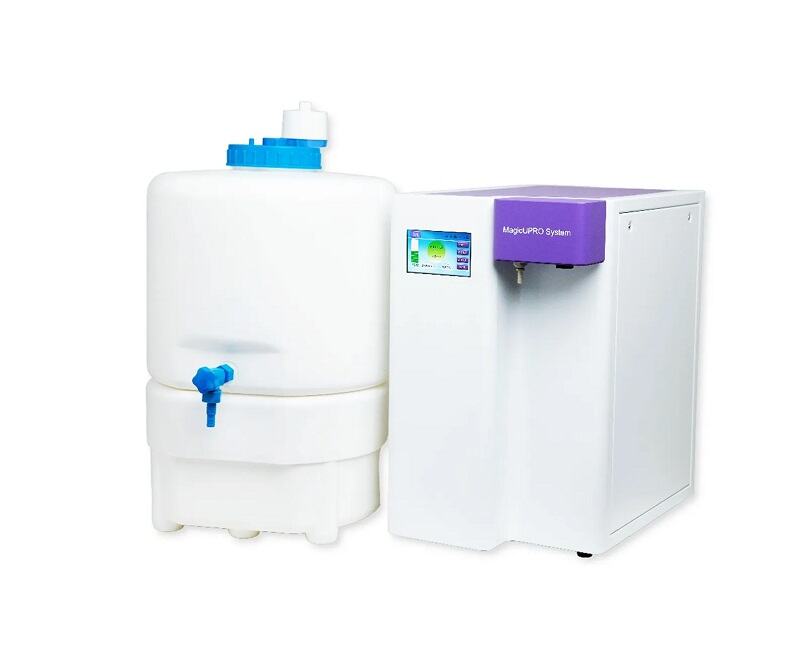
Laboratory Water Specifications
The source water (feedwater) used for analytical laboratory applications should consist of potable water or water of appropriate purity.
Laboratory water for analytical purposes is classified into three grades: Grade I, Grade II, and Grade III.
☆ Grade III Water: This represents the lowest grade of laboratory-purity water. It is recommended for applications such as washing glassware, filling water baths and autoclaves, and serving as the feedwater for ultrapure water systems.
☆ Grade II Water: Generally used for routine laboratory applications, such as the preparation of buffers, pH solutions, and microbiological culture media; supplying water to ultrapure water systems, clinical biochemistry analyzers, incubators, and accelerated aging chambers; and preparing reagents for chemical analysis or synthesis.
☆ Grade I Water: Typically reserved for rigorous experimental applications, such as the preparation of HPLC mobile phases; the preparation of GC blanks and sample dilutions; high-precision analytical techniques (e.g., HPLC, AA, ICP-MS); the preparation of buffers and mammalian cell culture media; the preparation of reagents for molecular biology applications (e.g., DNA sequencing, PCR amplification); and the preparation of solutions for electrophoresis and hybridization experiments.

Standard Water Quality Classifications
01. Pure Water
Pure water—also referred to as purified water—represents the lowest level of purification; specifically, it corresponds to the national standard for Grade III laboratory water. It typically exhibits an electrical conductivity ranging from 1 to 10 μS/cm. It can be produced using a single weak-base anion exchange resin, reverse osmosis, or single distillation; it contains no additives, is colorless and transparent, and is safe for direct consumption. "Space water" and distilled water sold on the market are both classified as pure water. Typical applications for pure water include the cleaning of glassware and use in washing machines.
02. Deionized Water
Deionized water represents a water quality level situated between standard pure water and Laboratory Grade II water; its conductivity typically ranges from 0.1 to 1.0 μS/cm (with a resistivity between 1.0 and 10.0 MΩ·cm). It is produced using mixed-bed ion exchange involving strong anion exchange resins. While it may contain relatively higher levels of organic matter and bacterial contamination, it is capable of meeting a variety of needs, such as cleaning, preparing analytical standard samples, formulating reagents, and diluting samples.
03. Laboratory Pure Water
Typically, "Laboratory Pure Water" refers to water that meets the national standard for Grade II water. This standard demands not only high purity in terms of ionic content but also low concentrations of organic matter and microorganisms. Typical specifications include a conductivity of <0.1 μS/cm (resistivity >10 MΩ·cm), a Total Organic Carbon (TOC) content of less than 50 ppb, and a bacterial count of less than 1 CFU/mL. This water quality is suitable for a wide range of applications, ranging from reagent preparation and solution dilution to the formulation of nutrient media for cell culture and microbiological research. Laboratory pure water can be produced via double distillation, or by integrating multiple technologies—such as reverse osmosis (RO) and ion exchange/EDI—potentially combined with adsorption media and UV irradiation.

04. Laboratory Ultrapure Water
"Laboratory Ultrapure Water" represents the ideal water quality, surpassing the standards for Laboratory Grade I water. In terms of resistivity, organic content, particulate matter, and bacterial levels, it approaches the theoretical limits of purity. It is produced by first undergoing preliminary purification via ion exchange, RO membranes, or distillation, followed by a final polishing step using nuclear-grade ion exchange resins to achieve ultrapure water. Typically, ultrapure water achieves a resistivity of 18.2 MΩ·cm, a TOC content of <10 ppb, and is filtered to remove particles of 0.1 μm or smaller, with a bacterial count of less than 1 CFU/mL. Ultrapure water is suitable for meeting the requirements of various precision analytical experiments, such as High-Performance Liquid Chromatography (HPLC), Ion Chromatography (IC), and Inductively Coupled Plasma Mass Spectrometry (ICP-MS).
Common Water Purification Technologies
Common purification methods include ion exchange, activated carbon adsorption, microporous membrane filtration, reverse osmosis desalination, ultrafiltration, and UV digestion for TOC reduction.
How to Select a Pure Water System
Selection should be based on the following key points:
Clarify the Feedwater Source: It is essential to determine whether the system will utilize municipal tap water or pre-purified water (such as deionized or distilled water) as its input source. If the quality of the municipal tap water is poor (e.g., TDS ≥ 300 ppm), enhanced pre-treatment modules—such as water softeners, KDF filters, etc.—should be added to the configuration.
Determine Water Consumption: User water requirements must be evaluated based on the following aspects: Water Dispensing Method—specifically, whether water is drawn continuously or intermittently during operation, and whether there are specific requirements regarding outlet pressure, storage tanks, tubing, etc.; Peak Demand—the duration of peak usage periods and the corresponding volume requirements, which help determine the appropriate machine specifications and configuration; and Daily Consumption—calculated separately for pure water and ultrapure water requirements to further refine the selection of the specific product model.
Align with Experimental Requirements: Select the system based on the specific standards of the analytical tests being performed. Consider whether the experiments impose specific limits on parameters such as TOC (Total Organic Carbon), bacterial count, pyrogens, or particulate matter. In other words, identify the specific application area or the analytical instruments with which the system will be paired—such as Atomic Absorption Spectrometry (AAS), microbiological analysis, general chemistry, cell culture, biochemical analysis, etc. Clearly defining these parameters ensures the precise selection of the appropriate product model and specifications.
I. Introduction to EDI Ultrapure Water Systems
EDI (Electrodeionization) ultrapure water treatment equipment—also known as an electrodeionization system—represents a novel technology for producing ultrapure (or high-purity) water by organically combining electrodialysis membrane separation technology with ion exchange technology. It utilizes the polarization phenomenon inherent in the electrodialysis process to electrochemically regenerate the ion exchange resins packed within the system's dilute water chambers. Operating under the influence of a DC electric field, the system drives the directional migration of dissolved ions (electrolytes) within the water as they pass through the separation membranes; by leveraging the selective permeability of these membranes toward specific ions, the system effectively purifies the water.
II. Basic Working Principles of EDI
EDI is a pure water production technology that integrates ion exchange, ion exchange membrane, and ion electromigration (electrodialysis) technologies. This technology leverages the deep desalination capabilities of ion exchange to overcome the limitations of electrodialysis—specifically, its potential for incomplete desalination due to polarization effects. Simultaneously, it harnesses the electrodialysis polarization phenomenon to induce the dissociation of water molecules, generating H+ and OH- ions. These generated ions serve to continuously regenerate the ion exchange resins, thereby ensuring that the resins remain in their optimal state for effective purification. An EDI stack primarily consists of an alternating arrangement of cation exchange membranes, concentrate compartments, anion exchange membranes, diluate compartments, and positive and negative electrodes. Ion exchange resins are packed between the cation and anion exchange membranes to form individual treatment units, which constitute the diluate compartments; these units are separated from one another by mesh spacers, thereby forming the concentrate compartments. Under the influence of a direct current electric field, cations and anions within the ion exchange resins in the diluate compartments migrate—along the channels formed by the resins and membranes—toward the negative and positive electrodes, respectively. Cations pass through the cation exchange membranes, while anions pass through the anion exchange membranes, entering the concentrate compartments to form a concentrate stream. Simultaneously, cations and anions present in the EDI feed water undergo exchange with the hydrogen ions and hydroxide ions within the ion exchange resins, resulting in the production of ultrapure water (or high-purity water). The application of a "super-limiting current" induces the electrolysis of water, generating a copious supply of hydrogen ions and hydroxide ions that continuously regenerate the ion exchange resins. In contrast to traditional ion exchange processes—where resins require intermittent chemical regeneration once saturated—the resins within an EDI stack are continuously regenerated through the electrolysis of water; thus, the operation is continuous and requires no chemical regeneration using acids or bases.
An EDI system separates the feed water into three distinct streams: a pure water stream, a concentrate stream, and an electrode rinse stream. The pure water stream (90–95% of the total flow) constitutes the final product water; the concentrate stream (5–10%) can be recycled for further processing; and the electrode rinse stream (1%) is discharged.

III. Characteristics of EDI Systems
EDI systems do not require chemical regeneration and are capable of continuous operation; consequently, they eliminate the need for the acid and alkali solutions—as well as the wastewater discharge—typically associated with the regeneration of mixed-bed ion exchange equipment in traditional water treatment processes. Their key characteristics are as follows:
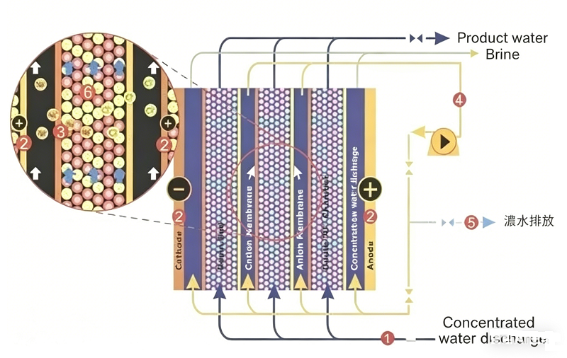
The Basic Water Purification Process of EDI:
(1) Continuous operation, resulting in stable product water quality.
(2) Easy to implement fully automated control.
(3) No need for acid or alkali regeneration.
(4) No downtime caused by regeneration; saves on regeneration water and eliminates the need for regeneration wastewater treatment facilities.
(5) High water recovery rate (up to 95%).
EDI units belong to the category of fine water treatment systems. They are typically used in conjunction with Reverse Osmosis (RO) to form an ultrapure water treatment system comprising pretreatment, RO, and the EDI unit, thereby replacing the mixed-bed ion exchange equipment found in traditional water treatment processes. The feedwater requirement for an EDI unit is a resistivity of 0.025–0.5 MΩ·cm—a standard that RO units are fully capable of meeting. EDI units can produce ultrapure water with a resistivity exceeding 15 MΩ·cm.
For high-purity water systems, the RO + EDI process represents an ideal choice—whether one considers factors such as water quality, performance, and operation, or aspects such as operating costs and environmental protection.
III. Advantages and Disadvantages of Various Technical Processes for EDI Equipment
Currently, there are approximately three main technical approaches utilized by complete EDI ultrapure water systems to produce ultrapure water. Each of these three processes possesses its own distinct advantages as well as disadvantages. The first approach is the traditional method of producing ultrapure water using ion exchange resins. This process offers clear advantages: the initial capital investment for the equipment is low, and the equipment occupies a relatively small footprint. However, after prolonged operation, the resins require regeneration; this regeneration phase results in significant waste of acids and alkalis, as well as associated pollution, making it a less environmentally friendly option.
Nowadays, ultrapure water system processes generally fall into three major categories; other processes are essentially derivatives created by combining and configuring these three fundamental categories in various ways. The advantages and disadvantages of these three processes are listed below:
1. The first process employed by specialized EDI ultrapure water systems (typically for the electronics industry) relies primarily on ion exchange resins. Its advantages lie in the low initial capital investment and the minimal space requirements; however, its disadvantages are equally evident: it necessitates frequent regeneration, which causes a certain degree of environmental damage.
2. The second process utilizes Reverse Osmosis (RO) technology as a pretreatment stage. The disadvantages of this process are even more significant than those of the first: the initial capital investment required is substantially higher than that of the first method. Its sole advantage is that the regeneration intervals for the specialized EDI ultrapure water equipment are relatively longer; however, this process still carries a certain potential for environmental pollution. 3. The third process also utilizes a reverse osmosis unit as the pretreatment equipment. Currently, this third method represents the most economical and environmentally friendly process available for producing ultrapure water; it eliminates the need for equipment regeneration procedures and results in virtually no environmental pollution. However, its drawback lies in the fact that the initial capital investment required remains relatively high compared to the two methods mentioned above.
III. Assessment of Contamination in EDI Equipment and Cleaning Methods
EDI Fouling Assessment and 8 Cleaning Methods
Although the inlet water conditions for EDI modules significantly reduce the likelihood of internal blockage, as equipment operating time extends, it remains possible for blockages to develop within the internal water channels of the EDI modules. This is primarily due to the presence of high concentrations of dissolved solutes in the EDI feed water, which leads to the precipitation of salts within the concentrate chambers. If the feed water contains high levels of calcium and magnesium ions (hardness exceeding 0.8 ppm), CO2. and has a high pH value, the rate of precipitation will be accelerated. When such situations arise, chemical cleaning methods can be employed to clean the EDI modules and restore them to their original technical specifications.
Typically, the fouling or blockage of an EDI module can be assessed and determined based on the following criteria:
1. With inlet water temperature and flow rate remaining constant, the differential pressure between the inlet and product water sides increases by 45% compared to baseline data.
2. With inlet water temperature and flow rate remaining constant, the differential pressure between the concentrate inlet and concentrate outlet sides increases by 45% compared to baseline data.
3. With inlet water temperature, flow rate, and conductivity remaining constant, the quality of the product water (resistivity) declines significantly.
4. With inlet water temperature and flow rate remaining constant, the concentrate outlet flow rate decreases by 35%.
The primary causes of module blockage typically fall into the following categories:
1. Particulate/Colloidal Fouling
2. Inorganic Fouling
3. Organic Fouling
4. Microbial Fouling
EDI Cleaning Precaution: Before performing any cleaning or disinfection, please select the appropriate chemical reagents and familiarize yourself with the safety operating procedures. Under no circumstances should chemical cleaning be attempted while the power supply to the module remains connected.
The Distinction Between RO and UP in Ultrapure Water Systems
An ultrapure water system constitutes a complete, integrated unit; the product water generated by the Reverse Osmosis (RO) stage serves as the feed water for the Ultrapurification (UP) stage.
If the RO membrane fails, the entire burden of maintaining water quality falls upon the downstream UP components, leading to the rapid depletion of expensive ultrapurification cartridges. Therefore, maintaining the RO system in good condition is the fundamental prerequisite for ensuring the stable and economical operation of the entire ultrapure water system.
01. RO (Reverse Osmosis): Also known as reverse osmosis water, this serves as the core workhorse of primary purification.
Function: By utilizing high pressure to force water through a semi-permeable membrane with extremely small pores (the RO membrane), it can remove 95%–99% of impurities from the water.
Includes: Ions (such as calcium, magnesium, sodium, chloride, etc.), organic matter, particulate matter, colloids, and microorganisms (bacteria, viruses, etc.).
Output Water Quality: Pure water. Its resistivity typically ranges from 1 to 10 µS/cm (i.e., 0.001–0.01 MΩ·cm). While it does not meet ultra-pure water standards, it serves as general-purpose pure water for laboratories and can be used for reagent preparation, cleaning, and similar applications.
02. UP (Ultra-Pure Water): Also known as ultra-pure water, this represents the final stage of deep refinement.
Function: It performs the ultimate purification on the "pure water" produced by the RO stage to achieve the theoretically highest level of purity. It is a multi-step process—a combination of various technologies—
Typically Includes: Ion exchange resins: For the deep removal of residual trace ions, bringing the resistivity up to 18.2 MΩ·cm.
UV sterilization: To destroy the DNA of microorganisms in the water, ensuring thorough sterilization.
Ultrafiltration/Microfiltration: To remove any minute particulate matter, bacteria, and—most importantly—pyrogens (endotoxins), which is critical for cell culture applications.
Output Water Quality: Ultra-pure water. It possesses a resistivity of 18.2 MΩ·cm and is virtually free of any ions, organic matter, particulates, or microorganisms.
Why Does the Resistivity Value of an Ultra-Pure Water System Typically Not Exceed 18.25 MΩ·cm?
During the operation of ultra-pure water systems, we frequently encounter or hear references to a specific resistivity value: 18.25 MΩ·cm. What exactly does this resistivity value indicate? Why is the figure specifically 18.25 MΩ·cm? Is it possible to achieve higher values—for instance, 20.25 MΩ·cm? Today, we will explore why the resistivity value of an ultra-pure water system typically does not exceed 18.25 MΩ·cm.
1. Understanding Resistivity Values
To analyze the questions raised above, we must first gain a basic understanding of resistivity values. Water bodies naturally contain both anions and cations; these ions serve as the conductive medium within the water. Measuring the resistivity of water provides an indirect indication of its purity level and its ionic content. Generally speaking, the lower the ion concentration in the water, the lower the conductivity, the poorer its electrical conduction properties, and the higher its resistivity; conversely, the higher the ion concentration, the higher the conductivity, the better its electrical conduction properties, and the lower its resistivity.
2. Why is the value 18.25 MΩ·cm?
At 25°C, the dissociation constant of water is 1.01 × 10 ⁻¹⁴. This implies that 1 mole of water molecules will inevitably dissociate to yield 10 ⁻⁷ moles each of H ⁺ and OH ⁻ ions. Theoretically, water that is completely free of impurities (with a total salt concentration below 1 ppb) will still exhibit a faint degree of conductivity due to this self-dissociation, with a conductivity of approximately 0.055 μS/cm. Since resistivity and conductivity are reciprocal values, the corresponding resistivity is 18.25 MΩ·cm (specifically, the resistivity value at 25°C when the H ⁺ and OH ⁻ ions are in ionization equilibrium). Yupu Ultrapure Water Systems feature a streamlined design and superior build quality, providing you with laboratory-grade pure and ultrapure water that fully complies with the Chinese National Standard GB6682-2008.
3. Why can the resistivity not exceed 18.25 MΩ·cm?
It is important to note that 18.25 MΩ·cm represents the resistivity of an ultrapure water system under ideal conditions at 25°C; it signifies the absolute limit of purity for ultrapure water at this specific temperature. In other words, this state implies that—aside from water molecules, H ⁺ ions, and OH ⁻ ions—absolutely no other substances are present in the water. The moment any impurities are introduced, the conductivity increases, causing the resistivity to decrease. Consequently, the resistivity value at 25°C can never exceed 18.25 MΩ·cm.
As is readily apparent, any discussion regarding the calculation of resistivity invariably involves a reference to "temperature." This is because resistivity is significantly influenced by temperature fluctuations. The lower the temperature, the fewer H ⁺ and OH ⁻ ions dissociate, resulting in a correspondingly higher resistivity value; conversely, the higher the temperature, the more H ⁺ and OH ⁻ ions dissociate, resulting in a correspondingly lower resistivity value. Within the water treatment industry, it is standard practice to apply temperature compensation to resistivity measurements taken at various temperatures, converting them to a standardized equivalent value at 25°C. This ensures that users can accurately monitor and assess the real-time quality of their water supply. Generally speaking, if no specific temperature is specified for a resistance value, it is assumed by default to be 25°C. Therefore, the previously mentioned value of 20.25 MΩ·cm is indeed plausible. However, this figure has not undergone temperature compensation; once compensated, the resulting value would not exceed 18.25 MΩ·cm.
Contact below if you would like to get a reply quicker.
Our company was founded in 2011.Our company specializes in the R&D, production, and manufacturing of molecular biology research instruments.
+86 10-53676895
1368690224@qq.com
No.1 Xinghuo Road, Fengtai District, Beijing
Copyright ©2025 Huatai Hehe (Beijing) Trading Co., LtdAll Rights Reserved.sitemap.xml

 English